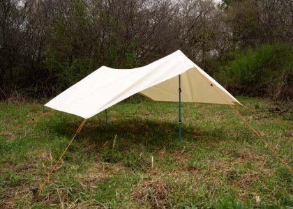
The promise of indefinite off-grid camping hinges on one critical capability: continuous power generation from your rooftop real estate. Yet most overlanders hesitate to permanently modify their premium hard-shell tents with drill holes that void warranties, compromise waterproofing, and create irreversible structural alterations. Flexible solar panels can be mounted to hard-shell rooftop tents using industrial-grade adhesive bonding systems, specialized mounting brackets with existing tent hardware integration, or magnetic attachment solutions—each method achieving 80+ mph wind resistance without penetrating the shell surface. This guide examines mounting methodologies validated through thousands of miles of expedition testing, comparing adhesion chemistry, load distribution engineering, and long-term durability across temperature extremes and UV exposure. You’ll learn precise surface preparation protocols, weight distribution calculations, electrical integration strategies, and troubleshooting solutions for the most common installation failures.
Table of Contents
- Why avoid drilling into hard-shell rooftop tents?
- What types of flexible solar panels work best for rooftop tent integration?
- Which adhesive bonding systems provide permanent, weather-resistant mounting?
- How do mechanical bracket systems attach without shell penetration?
- What surface preparation ensures maximum adhesive bond strength?
- How to calculate optimal panel positioning for maximum solar exposure?
- What wiring and electrical integration methods prevent water infiltration?
- How to maintain and inspect adhesive-mounted solar installations?
Why avoid drilling into hard-shell rooftop tents?
Drilling mounting holes through hard-shell rooftop tents creates three critical failure points: compromised structural integrity in composite materials designed with specific load-bearing geometries, warranty voidance on premium tents costing $3,000-6,000, and water infiltration pathways that accelerate interior degradation despite sealant application. Understanding these risks clarifies why adhesive and bracket-based solutions represent superior engineering approaches for solar integration.
Hard-shell tent construction utilizes fiberglass, ABS plastic, or aluminum composite panels engineered with calculated thickness, rib patterns, and material density to achieve target strength-to-weight ratios. Each drilled hole removes load-bearing material and creates stress concentration points where cracks initiate during vibration and thermal cycling. Composite materials particularly suffer from delamination radiating outward from penetration points, progressively weakening structural performance over 12-24 months.
Warranty implications extend beyond manufacturer coverage. Most rooftop tent warranties explicitly exclude damage resulting from modifications, meaning even unrelated failures may be denied if drilling is discovered during inspection. Insurance claims for accident damage similarly face scrutiny when non-factory modifications exist.
Water infiltration represents the most insidious long-term consequence. Despite proper sealant application at installation, UV degradation, thermal expansion differentials, and vibration-induced movement create microscopic gaps within 6-18 months. Water entering through compromised penetrations migrates between composite layers, causing core material deterioration, mold growth, and electrical system corrosion invisible from external inspection.
Engineering Principle: Adhesive bonding distributes loads across entire contact areas rather than concentrating stress at discrete penetration points, providing superior structural performance in dynamic loading conditions typical of highway travel and off-road articulation.
What types of flexible solar panels work best for rooftop tent integration?
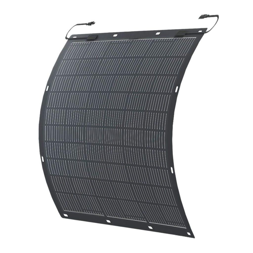
Monocrystalline ETFE-coated flexible solar panels in the 100-175 watt range with thickness under 3mm and weight below 5 pounds deliver optimal performance-to-profile ratios for rooftop tent mounting, offering 18-23% conversion efficiency while maintaining flexibility sufficient to conform to curved shell surfaces without stress cracking. Panel selection must balance power output requirements, aerodynamic impact, weight distribution, and adhesive compatibility.
Power Output Optimization
Most overlanding electrical systems require 200-400 watts of solar capacity for sustainable operation of refrigerators, lighting, device charging, and tent air conditioning during multi-day stationary camping. A typical hard-shell rooftop tent provides 12-18 square feet of usable mounting surface, accommodating:
- Single 160-175W panel: Covers 80-90% of tent surface, maximizes output, creates significant aerodynamic profile
- Dual 100W panels: Allows strategic positioning around tent hardware, reduces individual panel size/weight
- Triple 50-60W panels: Provides installation flexibility, easier damage replacement, complicates wiring
Calculate your power requirements using actual device consumption data rather than manufacturer ratings. A 12V compressor refrigerator typically consumes 30-50 amp-hours daily; LED lighting 5-10 Ah; device charging 10-15 Ah. Add 25% safety margin and divide by average daily sun hours in your operating regions (4-6 hours for most North American locations).
Material Technology Comparison
| Panel Type | Efficiency | Flexibility | Weight (100W) | Durability | Cost |
| Monocrystalline ETFE | 20-23% | Excellent (30° bend) | 4-5 lbs | 5-7 years | $150-220 |
| Polycrystalline | 15-18% | Good (20° bend) | 5-6 lbs | 4-6 years | $100-150 |
| Amorphous thin-film | 10-12% | Superior (45° bend) | 3-4 lbs | 3-5 years | $80-120 |
| SunPower Maxeon | 22-24% | Good (25° bend) | 4.5-5.5 lbs | 7-10 years | $250-350 |
ETFE (Ethylene Tetrafluoroethylene) coating provides critical advantages over PET plastic alternatives: superior UV resistance (maintains 85%+ efficiency after 5 years), temperature tolerance (-40°F to 180°F), and abrasion resistance critical for off-road debris impact.
Physical Specifications for Rooftop Integration
Thickness: Panels under 3mm allow effective adhesive bonding with minimal aerodynamic profile increase. Thicker panels (4-6mm) create larger leading edges that trap wind and generate lift forces potentially exceeding adhesive bond strength at highway speeds.
Weight distribution: Target maximum 0.4 pounds per square foot additional roof loading. A 160W flexible panel weighing 5 pounds distributed across 15 square feet adds 0.33 lb/sq ft—well within safe limits for composite shells designed for 165-pound occupant loads.
Mounting surface: Flat-back panels with full-surface contact area achieve superior adhesion compared to panels with textured backing or integrated mounting grommets that reduce effective bonding surface by 25-40%.
Which adhesive bonding systems provide permanent, weather-resistant mounting?
3M VHB (Very High Bond) 5952 acrylic foam tape and Sikaflex-252 polyurethane construction adhesive represent the two proven permanent bonding solutions for rooftop tent solar mounting, each achieving 80+ mph wind resistance and 100% waterproof sealing when properly applied to prepared surfaces, with VHB offering cleaner installation and Sikaflex providing superior gap-filling for irregular surfaces. The choice between systems depends on surface geometry, temperature conditions during installation, and long-term serviceability requirements.
3M VHB Acrylic Foam Tape Systems
VHB technology utilizes viscoelastic acrylic foam that flows into microscopic surface irregularities, creating molecular-level adhesion without chemical curing. The 5952 formulation specifically designed for outdoor applications provides:
Bond strength: 90+ pounds per square inch (psi) after 72-hour cure at 70°F, increasing to 120+ psi after one week Temperature range: -40°F to 300°F operational; bonds effectively when applied above 50°F UV stability: No degradation after 2000+ hours accelerated weathering equivalent to 5-7 years outdoor exposure Conformability: 0.045″ thick foam compresses to accommodate surface variations up to 0.020″
Installation procedure for maximum bond strength:
- Apply tape to panel backing at 70-80°F ambient temperature
- Remove liner and position panel, applying moderate pressure across entire surface
- Use roller to apply 15 psi pressure (firm hand pressure) from center outward
- Allow 20 minutes before final positioning adjustments
- Avoid stress on bond for 72 hours during full cure development
VHB advantages include reversibility (debonding solvents available for future removal), clean installation without liquid adhesive mess, and consistent thickness that prevents squeeze-out onto visible surfaces. Limitations involve strict surface preparation requirements and reduced performance on highly textured or porous surfaces.
Sikaflex Polyurethane Construction Adhesive
Sikaflex-252 represents marine-grade elastic polyurethane adhesive engineered for permanent bonding of dissimilar materials in dynamic loading conditions:
Bond strength: 300+ psi tensile strength after seven-day cure Elongation: 400% elasticity accommodates differential thermal expansion between panel and shell Gap filling: Effective with surface gaps up to 0.125″, ideal for slightly irregular tent surfaces Chemical cure: Moisture-activated curing independent of temperature (although rate varies)
Application technique for structural bonding:
- Apply continuous 1/4″ bead around panel perimeter plus cross-pattern in center
- Press panel firmly into position, allowing adhesive to spread to 1/8-3/16″ thickness
- Secure with temporary weights (5-10 lbs distributed) or masking tape to prevent movement
- Allow 24-hour initial cure before removing temporary support
- Full structural strength develops over seven days
Sikaflex excels in cooler installation conditions (down to 40°F), irregular surface bonding, and applications requiring maximum ultimate strength. The working time of 15-20 minutes allows positioning adjustments, while elastic properties prevent stress concentration at bond edges during thermal cycling.
Hybrid Approach for Maximum Security
Professional installations often combine both systems: VHB tape provides immediate holding power and uniform thickness control, while Sikaflex applied to panel perimeter creates a secondary waterproof seal and adds 30-40% to ultimate bond strength.
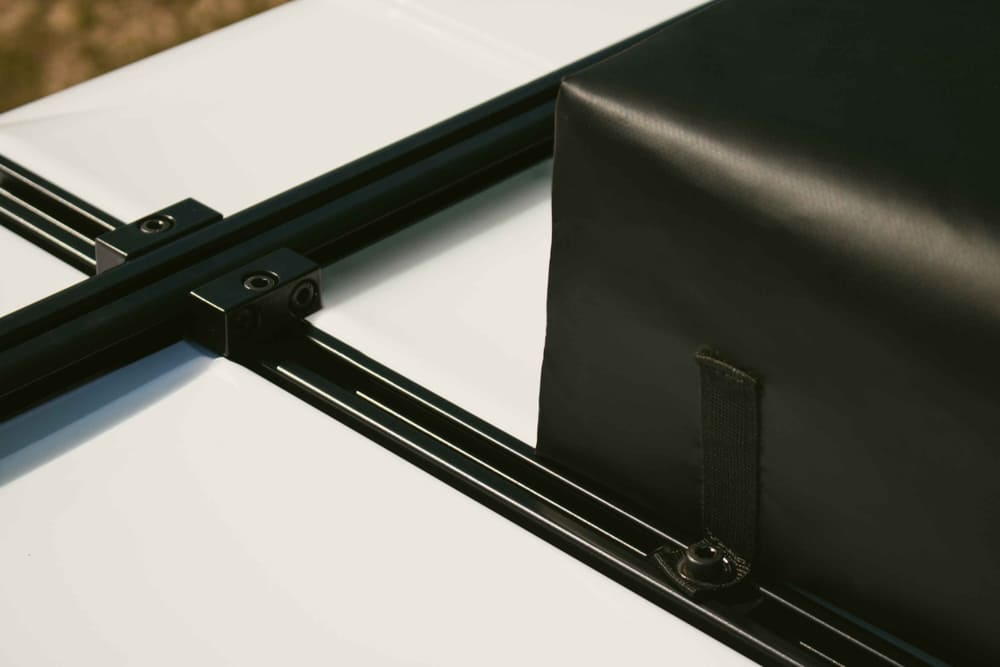
How do mechanical bracket systems attach without shell penetration?
Specialized mounting brackets utilize existing tent hardware attachment points—hinge bolts, gas strut mounting locations, and perimeter trim fasteners—to create load-bearing frameworks that support solar panels through clamping force rather than shell penetration, achieving 60+ mph wind resistance while maintaining complete shell integrity and system reversibility. These systems sacrifice some installation simplicity compared to adhesive bonding but offer significant advantages for rental tents, warranty preservation, and applications requiring frequent panel removal.
Hardware Integration Mounting Points
Hard-shell rooftop tents contain multiple factory-installed fasteners that can be repurposed for solar mounting:
Hinge assemblies: The pivot hinges connecting upper and lower shells typically use M8-M10 bolts passing completely through the shell material. Replacing factory bolts with longer fasteners (typically 15-25mm additional length) accommodates aluminum bracket attachment using:
- Stainless steel mounting plates (3-4mm thickness) positioned between hinge hardware and shell
- Nylock nuts with threadlocker ensuring vibration resistance
- Rubber isolators preventing metal-to-shell contact and distributing loads
Gas strut mounting locations: Pneumatic struts supporting lid opening attach via through-bolts ideal for bracket integration. A typical four-person tent features 2-4 gas strut mounting points capable of supporting 15-25 pounds each.
Perimeter trim fasteners: Aluminum or plastic trim pieces covering shell edges use 6-12 screws or rivets per side. Replacing plastic rivets with stainless screws and adding backing plates creates additional mounting points along tent perimeter.
Frame Design Principles
Effective bracket systems distribute panel weight and wind loads across multiple mounting points:
Perimeter frame design: Aluminum extrusion (1″ × 1″ × 1/8″ wall) forming a rectangular frame matching tent dimensions, with panel adhered or mechanically fastened to frame. Frame attaches at 6-10 points around tent perimeter.
Cross-bar system: Two or three aluminum bars spanning tent width, secured at hinge and gas strut locations. Panel attaches to bars using VHB tape or thin-profile clamps. Minimizes material but creates flex points at unsupported panel areas.
Integrated rail system: Aluminum C-channel or T-slot extrusion running tent length, secured at multiple points. Panel slides into channel with silicone gasket providing waterproofing and vibration dampening.
| Bracket System Type | Wind Resistance | Aerodynamic Profile | Installation Complexity | Reversibility | Cost |
| Perimeter frame | Excellent (70+ mph) | Moderate (+0.5-0.8″) | High (custom fabrication) | Complete | $150-300 |
| Cross-bar | Good (60+ mph) | Low (+0.3-0.5″) | Moderate (some fabrication) | Complete | $80-150 |
| Integrated rail | Excellent (75+ mph) | Very Low (+0.2-0.4″) | Low (bolt-on) | Complete | $200-400 |
| Adhesive hybrid | Good (65+ mph) | Minimal (+0.1-0.2″) | Low (no fabrication) | Difficult | $50-100 |
Load Distribution Calculations
Calculate whether existing hardware can support combined static weight plus dynamic wind loading:
Static load: Panel weight (typically 4-6 lbs) plus frame weight (3-10 lbs) distributed across mounting points. Each mounting point should support maximum 5-8 lbs static load to maintain safety margins.
Dynamic wind load: At 70 mph, a 15 square foot panel experiences approximately 45-60 pounds of lift force (assuming 0.2 sq ft frontal area and 1.5 lift coefficient). Distributed across 6-8 mounting points: 6-10 lbs per point. Combined with static load: 11-18 lbs per mounting point—within capacity of properly installed hardware.
Vibration amplification: Off-road articulation can create momentary load spikes 2-3× static values. Design for 20-25 lb per mounting point maximum load including safety factor.
What surface preparation ensures maximum adhesive bond strength?
Achieving full-rated adhesive bond strength requires four-stage surface preparation: solvent cleaning to remove oils and contaminants, abrasion to increase surface area and mechanical interlocking, secondary solvent wipe to remove abrasion residue, and primer application on low-surface-energy materials—collectively increasing bond strength by 200-400% compared to unprepared surfaces. Inadequate surface prep represents the primary cause of adhesive bond failures in rooftop solar installations, with proper technique requiring 45-60 minutes per panel.
Stage 1: Solvent Cleaning
New hard-shell tents arrive with mold release agents, protective waxes, and manufacturing oils on surfaces. Even tents used for months accumulate road film, UV protectants, and atmospheric contamination.
Cleaning protocol:
- Use isopropyl alcohol (IPA) 70% or higher concentration (91% preferred)
- Apply to clean microfiber cloth, not directly to surface
- Wipe entire bonding area with moderate pressure
- Immediately follow with dry cloth to remove dissolved contaminants
- Repeat process minimum two times
- Allow 10-15 minutes for complete alcohol evaporation
Alternative solvents include acetone (aggressive, test compatibility first), denatured alcohol, or 3M General Purpose Adhesive Cleaner. Avoid household cleaners containing silicones, moisturizers, or fragrances that leave residues reducing adhesion.
Stage 2: Surface Abrasion
Microscopic surface roughness dramatically increases adhesive contact area and creates mechanical interlocking:
Abrasion technique:
- Use 180-220 grit aluminum oxide sandpaper for fiberglass/ABS shells
- Use 3M Scotch-Brite 7447 maroon hand pad for powder-coated aluminum
- Apply moderate pressure with random circular pattern
- Cover 100% of bonding area plus 0.5″ beyond panel edges
- Create visible dulling but avoid aggressive material removal
- Target Ra (surface roughness) of 60-100 microinches for optimal adhesion
After abrasion, visible surface should appear uniformly dull/matte rather than glossy. Over-aggressive abrasion (causing visible scratching or material removal) can reduce bond strength by creating stress concentrations and reducing effective contact area.
Stage 3: Post-Abrasion Cleaning
Sanding generates fine dust particles that prevent intimate adhesive contact:
- Blow off loose dust using compressed air or leaf blower
- Vacuum bonding area thoroughly
- Final IPA wipe using clean cloths (replace cloths when they show contamination)
- Allow 15-minute dry time
- Avoid touching prepared surface with bare hands (skin oils contaminate)
Perform “water break test” to verify cleanliness: mist prepared surface with water; if water beads rather than forming continuous film, contaminants remain—repeat cleaning until water sheets uniformly.
Stage 4: Primer Application (Material-Dependent)
Low-surface-energy materials including some plastics and all ETFE/PET panel backings require chemical primers to achieve rated bond strength:
3M 94 Primer: Universal primer for VHB applications on low-energy surfaces
- Apply thin, uniform coat using foam brush or lint-free cloth
- Allow 1-2 minutes to become tacky (do not over-apply)
- Bond within 30 minutes of primer application for maximum effectiveness
Sikaflex Primer 215: Specific to Sikaflex adhesives, penetrates plastic surfaces
- Apply sparingly to both surfaces (tent and panel backing)
- Dry time: 30-60 minutes before adhesive application
- Remains effective for 24 hours after application
Test primer compatibility on inconspicuous area before full application. Some primers attack certain plastics, causing clouding or softening.
Environmental Conditions
Surface preparation and adhesive application must occur within specific temperature and humidity ranges:
- Temperature: 65-85°F optimal; 50°F minimum for VHB; 40°F minimum for Sikaflex
- Humidity: Below 70% relative humidity prevents moisture interference
- UV exposure: Prep and install in shade; direct sunlight overheats surfaces and accelerates adhesive skinning
- Wind/dust: Enclosed or sheltered location prevents airborne contamination of prepared surfaces
Consider using portable infrared heaters or heat guns on low setting to warm surfaces in cooler conditions, achieving optimal bonding temperature even when ambient conditions are marginal.
How to calculate optimal panel positioning for maximum solar exposure?
Optimal solar panel placement on rooftop tents requires balancing three variables: sun angle optimization through longitudinal orientation aligned with vehicle travel direction (typically north-south in Northern Hemisphere), aerodynamic positioning forward of the tent centerline to minimize drag coefficients, and structural weight distribution centering panel mass over primary support members to prevent cantilevered stress concentrations. Mathematical optimization using your primary camping latitudes and seasonal usage patterns can increase average daily energy capture by 15-25% compared to arbitrary placement.
Solar Geometry Fundamentals
Solar panels generate maximum power when oriented perpendicular to incoming sunlight. Since rooftop tents remain horizontal during stationary camping, optimization focuses on minimizing angle deviation throughout the day.
Sun position varies by:
- Time of day: Azimuth angle changes ~180° from sunrise to sunset
- Season: Elevation angle varies ±23.5° between summer/winter solstices
- Latitude: Higher latitudes experience greater seasonal variation
For overlanding applications spanning multiple latitudes, optimize for average operating region. A panel mounted on a vehicle typically facing north-south while parked (driver instinctively parks for optimal tent access) receives relatively balanced east-west sun exposure as the sun tracks across the sky.
Longitudinal Positioning Strategy
Forward placement (front 40% of tent surface):
Advantages:
- Minimizes additional frontal area during highway travel
- Positions panel in cleaner airflow before turbulent wake zone
- Centers weight over stronger forward hinge area
- Provides easier access for cleaning and maintenance
Disadvantages:
- Potential shading from roof racks, light bars, or other accessories
- May interfere with tent opening mechanism depending on design
- Concentrates weight away from geometric tent center
Center placement (middle 40% of tent surface):
Advantages:
- Optimal weight distribution over primary support structure
- Minimizes shading from vehicle roof accessories
- Balanced aerodynamic impact
Disadvantages:
- Maximum aerodynamic profile height
- May complicate tent opening/closing operations
- Challenging wiring route to vehicle electrical system
Rear placement (rear 20% of tent surface):
Generally not recommended due to:
- Turbulent airflow zone creating panel lift and vibration
- Difficult wiring routing
- Potential interference with ladder deployment
- Shading from tent in deployed position
Tilt Angle Considerations
While rooftop installations maintain horizontal orientation, understanding lost efficiency guides realistic power expectations:
| Camping Latitude | Optimal Fixed Tilt | Horizontal Loss Factor | Practical Impact |
| 25-30°N (Florida, Texas) | 28° | 8-12% loss | Minimal—high solar resource compensates |
| 35-40°N (Mid-Atlantic, Southwest) | 37° | 12-18% loss | Moderate—size panels accordingly |
| 40-45°N (Northern states) | 42° | 18-25% loss | Significant—consider 25% oversizing |
| 45-50°N (Canada, N. Montana) | 47° | 25-35% loss | Major—may require supplemental charging |
These losses reflect annual averages. Summer camping at high latitudes actually benefits from horizontal mounting as sun reaches near-overhead positions, while winter camping suffers maximum penalties.
Shading Analysis and Mitigation
Even 10% panel shading can reduce output by 40-60% due to series-connected cell strings. Identify and eliminate shade sources:
Permanent obstructions: Roof racks, antennas, light bars must clear panel area by minimum 12″ to prevent shading during low sun angles (morning/evening).
Seasonal shading: Leafless deciduous trees provide less shade than evergreens. When selecting campsites, position vehicle to minimize tree shading during 10am-2pm peak solar hours.
Vehicle orientation: In Northern Hemisphere, parking with vehicle nose pointing south maximizes panel exposure. An east-west orientation loses approximately 20-30% daily production due to morning/afternoon shading from tent’s deployed position.
What wiring and electrical integration methods prevent water infiltration?
Waterproof electrical integration uses marine-grade cable glands penetrating tent shells at strategic low-points with redundant sealing—silicone adhesive primary seal, compression gasket secondary seal, and drip loop tertiary protection—while maintaining wire gauge sufficient for maximum current (10 AWG for 100W panels, 8 AWG for 175W+) and incorporating inline fusing within 18 inches of panel output to prevent fire hazards. Electrical failures from water infiltration account for 40-60% of rooftop solar system problems, making proper wiring execution critical for reliable operation.
Cable Entry Point Selection
Choose shell penetration locations that:
- Minimize water exposure: Lowest practical point on tent sides (water runs downward)
- Avoid hinge/stress zones: Minimum 4″ from hinges, gas strut mounts, or high-flex areas
- Align with tent interior: Direct access to battery/controller mounting location
- Facilitate drip loops: Allow wire to exit downward then curve upward inside tent
Front lower corners typically provide optimal balance of these factors, positioning cable exit below primary water flow paths while maintaining short runs to vehicle electrical systems.
Cable Gland Installation
Marine-grade cable glands provide compression sealing around wire jackets:
Installation procedure:
- Drill pilot hole 1/16″ smaller than gland diameter
- Deburr hole edges thoroughly (burrs cut wire insulation)
- Apply marine silicone sealant to gland base and hole perimeter
- Thread wire through gland before tightening
- Insert gland, tightening compression nut to manufacturer torque specification
- Apply additional sealant bead around exterior perimeter
- Create drip loop—wire exits downward 3-4″, then curves upward to entry point
Test seal by spraying pressurized water directly at entry point from multiple angles. Any penetration indicates inadequate sealing requiring disassembly and resealing.
Wire Routing and Strain Relief
Vibration and thermal expansion create wire movement that fatigues conductors and loosens connections:
- Use flexible wire (Class K stranding minimum) rather than solid core
- Secure wire to tent structure every 12-18″ using adhesive-backed cable ties
- Leave 2-3″ slack loops at transition points to accommodate thermal expansion
- Protect wire from sharp edges using grommets or split loom
- Route away from heat sources (exhaust vents, friction points)
Connector Selection
All connectors must achieve IP67 (dust-tight, waterproof to 1m submersion) or better:
MC4 connectors: Industry standard for solar applications, UV resistant, rated 20+ amps Anderson Powerpole: Modular 15/30/45 amp versions, excellent for system expansion Deutsch connectors: Automotive-grade, vibration resistant, premium cost
Apply dielectric grease to all connection interfaces before mating. This prevents corrosion and improves waterproofing.
Electrical Protection
Fusing: Install appropriately-sized fuse within 18″ of panel positive output. Fuse rating should exceed maximum panel output by 25% (175W panel at 18V = 9.7A, use 12A fuse).
Reverse polarity protection: Solar charge controllers include built-in protection, but dedicated inline diode prevents backfeed damage if controller fails.
Disconnect capability: Include removable connector near tent-vehicle transition point for system isolation during tent removal or servicing.
How to maintain and inspect adhesive-mounted solar installations?
Adhesive-bonded solar installations require quarterly visual inspection of bond edges for separation or degradation, annual panel removal for adhesive condition assessment on critical systems, and proactive resealing of any edge gaps exceeding 1/16″ using matching adhesive before moisture infiltration causes progressive bond failure—proper maintenance extending system service life from typical 3-5 years to 7-10+ years. Neglected installations often fail catastrophically, with panels departing vehicles at highway speeds creating safety hazards and expensive damage.
Quarterly Visual Inspection Protocol
Every 3 months or 5,000 miles:
- Edge examination: Inspect full panel perimeter for visible gaps between panel and tent surface
- Surface deformation: Look for bubbling, wrinkling, or lifting indicating adhesive degradation
- Wire entry points: Verify sealant remains intact without cracking or separation
- Panel surface: Clean accumulated debris, inspect for physical damage
- Electrical connections: Verify connector integrity, check for corrosion
Document findings with dated photographs, establishing baseline for tracking progressive changes.
Edge Gap Remediation
Gaps under 1/16″ wide and under 2″ long require monitoring but not immediate action. Larger gaps require resealing:
- Clean gap thoroughly using IPA-soaked pipe cleaner or small brush
- Allow 30 minutes drying time
- Apply matching adhesive (Sikaflex or VHB tape) into gap using syringe applicator
- Smooth excess with finger (wear latex glove)
- Allow full cure before stress (24 hours minimum)
Annual Deep Inspection
Once yearly, assess bond integrity:
Lift test: At panel corners, apply gentle upward pressure (5-10 lbs force). No movement should be detectable. Any lifting indicates adhesive failure requiring full panel removal and rebonding.
Percussion test: Gently tap panel surface with knuckles while listening for hollow/dull sound changes indicating delamination.
Thermal imaging (advanced): Use FLIR camera to identify adhesive voids showing as cold spots during sunny operation—voids prevent heat transfer to tent shell.
When to Replace vs. Repair
Replace entire adhesive bond if:
- Separation exceeds 20% of panel perimeter
- Multiple separated areas appear across panel surface
- Visible adhesive degradation (crumbling, color change to yellow/brown)
- System age exceeds manufacturer adhesive service life rating
Repair is appropriate for:
- Isolated edge separations under 4″ length
- Corner lifting affecting less than 10% of bond area
- Wire entry point seal failures
- Surface contamination causing localized adhesion loss
Conclusion
Mounting flexible solar panels to hard-shell rooftop tents without drilling has evolved from experimental modification to proven engineering methodology, with adhesive bonding and bracket-based systems achieving wind resistance, waterproofing, and longevity comparable to or exceeding penetrating fastener installations. The critical success factors—proper surface preparation, appropriate adhesive chemistry selection, strategic positioning for solar and aerodynamic optimization, and marine-grade electrical integration—require methodical execution but demand no specialized tools or skills beyond patient attention to process.
VHB tape systems deliver the cleanest installation aesthetic and fastest application for well-prepared flat surfaces. Sikaflex polyurethane adhesive accommodates irregular surfaces and provides maximum ultimate bond strength for extreme conditions. Mechanical bracket systems preserve complete tent integrity for warranty-conscious users or rental applications, trading installation complexity for reversibility.
The 45-60 minutes invested in thorough surface preparation directly determines whether your installation performs flawlessly for seven-plus years or fails catastrophically within the first season. Surface contamination, inadequate abrasion, or primer omission on low-energy materials reduce bond strength by 60-80%, making preparation the highest-value investment in the entire installation process.
For overlanders serious about extended off-grid capability, rooftop solar integration has transitioned from luxury to necessity. The methods detailed in this guide enable that capability without compromising tent integrity, warranty coverage, or long-term reliability.
Partnering with Everlead Outdoor
Everlead Outdoor manufactures premium hard-shell rooftop tents with integrated solar compatibility engineering. Our tent shells feature reinforced mounting zones, pre-positioned cable entry provisions, and surface treatments optimized for adhesive bonding—eliminating the trial-and-error of aftermarket solar integration. As an ISO 9001-certified direct manufacturer specializing in luxury automotive camping solutions, we understand that true off-grid capability requires systems thinking: our rooftop tents work seamlessly with flexible solar panels, portable power stations, and tent air conditioners to create complete mobile living ecosystems. Whether you’re an overlanding brand seeking OEM solar-ready tent designs or an adventurer building your ultimate expedition vehicle, Everlead provides the engineering foundation for reliable off-grid power.
Connect with us: Email: [email protected] | Phone/WhatsApp: +86 13726240980